Anhedonia roast pork
- 8 Posts
- 29 Comments
Joined 2 years ago
Cake day: May 11th, 2024
You are not logged in. If you use a Fediverse account that is able to follow users, you can follow this user.
Chiliius

 2·10 months ago
I can’t waaaaiiiit, no i can’t wait
Ginkos are very common. They’re ancient trees, and almost went extinct, but they’re tolerant of the rather extreme conditions of an urban environment and very pollution resistant

 2·2 years ago
You may or may not be interested to hear that I took your warning to heart and I’m now planning on using an actual DC power supply, coupled with either a resistive or inductive ballast which will also be designed for that purpose.
I’m sure the original plan is easily workable for someone with training or education, but for an amateur, it was too far outside the box to find reliable information and feel confident in it
Caution noted, I appreciate the effort either way
After reading more, it seems like I’m simply looking for a choke that limits current to 1ish amps
I’ll probably be cranking up the current after I get it working, but this is a second step from the light bulb
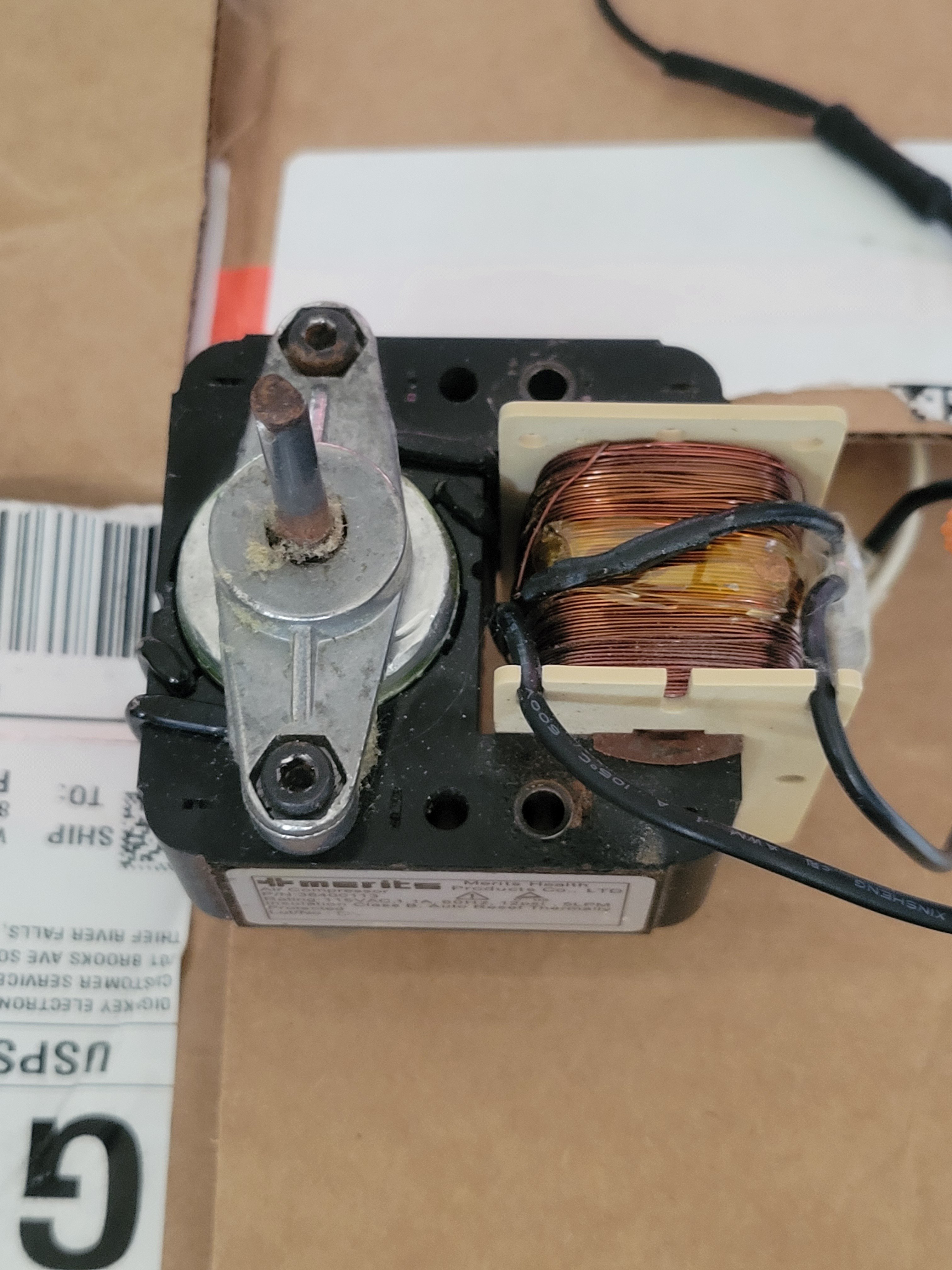
This is, hopefully, going to be functioning as a current- limiting ballast for a solid state tesla coil. So I need the 1.1A it draws, but not the motor.
I just wasn’t sure if that 1.1A would stay constant if it was just the primary coil, without the motor.
I agree it’s a weird question, but it’s because the instructions I’m following are very vague about what to use as a ballast. The guy says to test the circuit with an incandescent bulb, then use a hair dryer, toaster, or other household implement that draws a couple/few amps. I’m trying to figure out the bare minimum of components from a device that will still draw current
I just had a thought, if I’ve got a laptop charger or similar brick that supplies 5A DC, do you think there’s any reason that wouldn’t work?
Okay, it sounds like we’re more or less on the same page and that this is more of a workaround to achieve a certain amount of amperage, but in an uncommon way, that leaves a lot up to the imagination (introducing a bit of risk)
A solid state tesla coil. It’s needed to limit current, and is wired in series with a rectifier to turn 120V AC into stable DC
Its purpose is current-limiting
https://www.instructables.com/Simplest-POWERFUL-Solid-State-Tesla-Coil-SSTC/
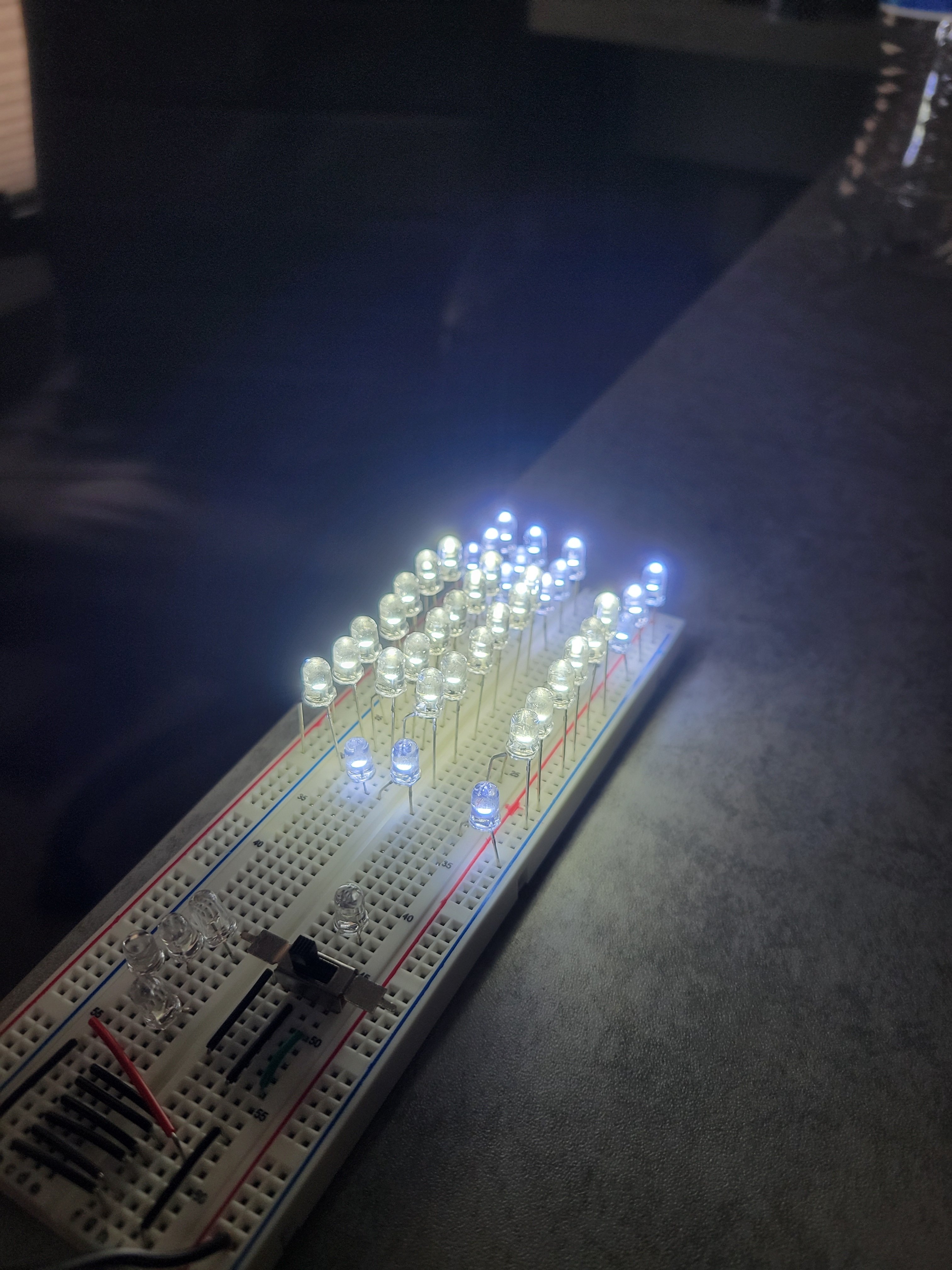
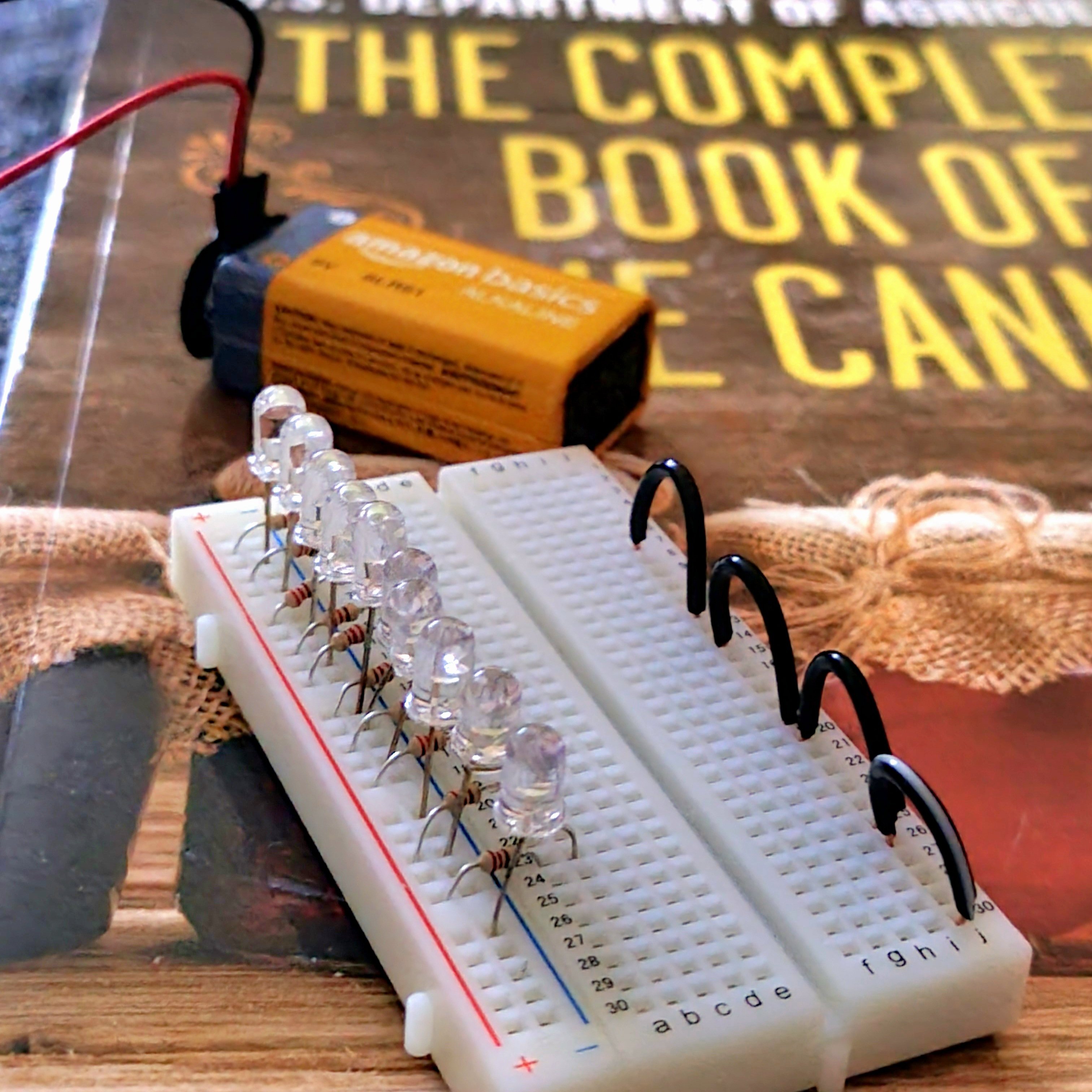
I’m the middle of reading your comment I realized what I did wrong when making it in the breadboard.
So I got the switch and parallel LEDs working, but the single LED connected directly to positive wouldn’t light. The resistor and LED made a loop back onto the same positive side of the breadboard, so the current had no reason to flow through them.
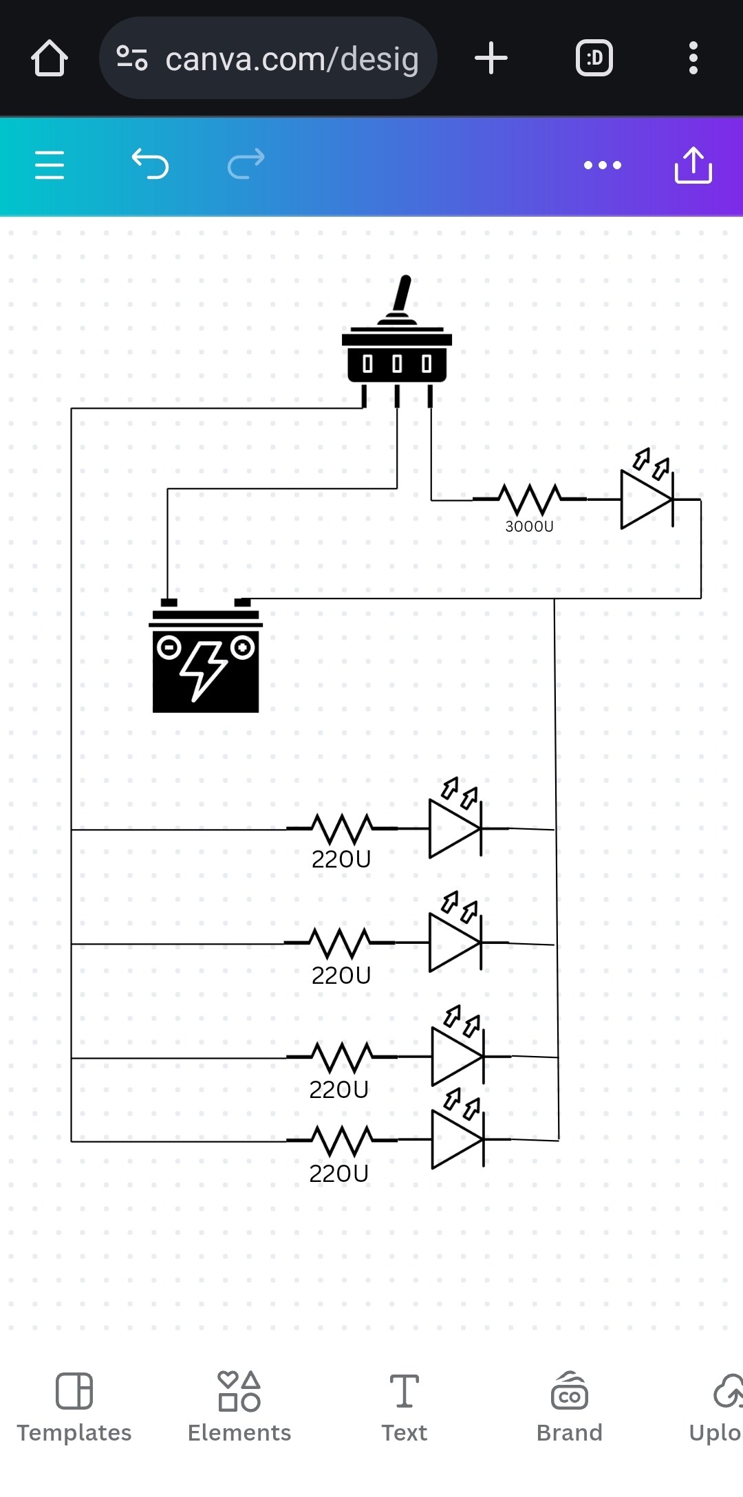
Something like this?
Also, are there any glaring issues with doing it like this?
Yep, the power source is a 7.5V wall wart
The lights are going to be on a wall, around 7’ up, with the power running straight down to an outlet. About halfway up will be a switch
Yeah, I’m not surprised help is limited without a diagram. Maybe I can get around to making one tonight
I still need to run the numbers to figure out exactly which transistor fits this application, but I feel like anything getting that hot isn’t properly matched to 8 LEDs
It is way confusing.
http://www.tv.com/shows/firefly/forums/correct-order-of-episodes-4587-20154/
Serenity (parts 1 & 2)
The Train Job
Bushwhacked
Shindig
Safe
Our Mrs. Reynolds
Jaynestown
Out of Gas
Ariel
War Stories
Trash
The Message
Heart of Gold
Objects in Space